The Artificial Lung demo shows the application of a KEEL based solution in a simple control application.
The concept being demonstrated shows the concept of a portable artificial lung that adapts to demand and pumps harder when the user's demand goes up. A basic level of demand is set to keep the person alive. This is a factory setting. There is a second demand setting that is dynamically adjusted. There is also a sensor that indicates either a dirty filter or some other restriction in the air flow. There is an alarm that is triggered if the air flow restriction is too high. The alarm is also triggered when the demand is excessive. There is also an alarm if the air repository exceeds limits (although this is not visible in the demo).
This is not a cognitive demonstration as is the case with some of the applications, but an adaptive control demonstration. Other cognitive features could be added, such as diagnostics and prognostics or alarm generation that takes several other sensor values into account: for example if it was tied into an emergency response system.
The code (bars and sliders shown below) is created by the KEEL toolkit. It is in the KEEL toolkit, where the relationships between the demand sensor, air flow sensor, and repository sensor and on/off switch are manipulated. The KEEL toolkit has a menu option to autogenerate the "code" that defines the behavior in C , C++, Microsoft C#, Java, Python, Microsoft Visual Basic, or PLC Structured Text code and others. The resulting solution is a very small footprint engine. This system is based on Compsim's patented and patent-pending KEEL technology that covers the toolkit user interface, Compsim's decision-making algorithms, and the resulting KEEL engine architecture.
The following image shows the design of the system from within the KEEL toolkit.
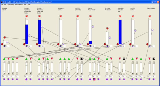
The vertical bars at the top of the screen image are indications of the Actions to be performed or Information Items being evaluated. The height of each of the bars indicates a relative level of action required or a level of importance/significance of that information item. The vertical scroll bars at the bottom of the screen are inputs (either external or internal). The wires between connection points define how one piece of information impacts another. While these images are probably not readable in this document, the design is easy to create and visualize in the KEEL toolkit. While in the design mode the user can "see" the design in action and graph the activity.
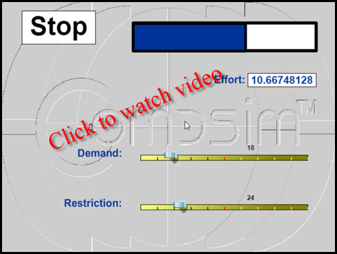
There is a button to START/STOP the operation of the artificial lung. An Alarm indicator below the start button will illuminate when the effort to operate the equipment is excessive. A horizontal bar to the right of the Start/Stop button is an indication of the amount of air in the oxygen repository. In its initial state, the repository is empty. At the bottom of the screen are two horizontal scroll bars used to indicate 1) demand for oxygen and 2) a simulation of a restriction in air flow as might be detected by a sensor. The restriction in air flow causes the "effort" to increase. This is shown in the Effort indicator at the lower right of the screen. To start the demo, click on the START button.
When the START button is depressed, the pump starts and the Repository is filled. This is done slowly, just to keep the patient at rest alive and at ease. You will see the oxygen repository fill from empty to an upper limit (inhale) and then see empty slowly (exhale). It will not completely empty when running.
The Demand scroll bar can be used to accelerate the inhale and exhale function. This could be driven by the patient's heart rate. The rate of inhale and exhale will increase. Should the demand exceed a predefined (factory set) rate, the alarm indicator will illuminate.
The Restriction scrollbar can be used to simulate a restriction in air flow. This causes an increase in effort and causes the pump to run faster (although this is somewhat hard to see in the demo - But it does.) You can see the increase in Effort expended in the indicator at the lower right. The image below shows the Alarm condition caused by Restricted Air Flow.
The demonstration applications on Compsim's web site are not intended to be tutorials on the use of the KEEL toolkit. If you are interested in learning more about Knowledge Enhanced Electronic Logic and KEEL technology, please contact Compsim at the phone number listed below.
|
Copyright , Compsim LLC, All rights reserved |